 Mold Making and Injection Molding: Two Separate Worlds
During the first 14 years of my career, when I was building and designing injection molds, gating and runners were not really a focus. In most cases mold making and Injection Molding are two different worlds, so in my case I had no idea what was going on over in the injection molding side. The gates and runners had no impact on my focus, which was to build robust tools. In 2002 when I made the switch from Mold Making to the Injection Molding arena, gating and runners were an area that jumped out at me right away as not really having any type of standard.
Gates and Runners
I started studying gates and runners when I was developing in mold de-gating with tab gates. To create a clean break, gate geometry and land were critical factors. I learned quickly that from mold to mold there was nothing consistent with gate geometry between material and part size. I saw large parts with gates half the size of the gates on a smaller part that were running the same material. I realized that gate orifice geometry was not a major focus for many injection molders. Gate location on the part was considered more important by far. My point of view led me to question many things as I saw opportunity to learn.
With the in-mold de-gating I needed to have the gate as thin as possible and minimal land to assist with a clean break. I started learning a lot about plastics pressures during this process, welding and modifying gates on numerous tools. Many people expressed their concerns with my focus on making the gates thinner, but they could give no specific examples to back up their objections. There was no standard specific geometry for gates and runners, which didn’t make sense, but because gate changes made people nervous it prevented them from learning.
Gating Modifications
Through the process of modifying gates on various tools I learned some interesting things: When an injection molder decreases the gate size or thickness, it doesn’t always mean plastic pressure will increase. When increasing a gate thickness or size it does not always mean the plastics pressures will drop. This is an assumption for many people, and it was during my first year in manufacturing that I really started to respect the process side and learn I could improve that window with tool modifications. Even modifications with gating.
Typically, when a gate size is made smaller you can expect to see a change in plastics pressure because of the reduced volume of the gate orifice. But just because the gate size or volume is increased or decreased, it does not mean a plastics pressure change will necessarily be noticed. I found out that when I decreased the gate thickness and had an increase of plastics pressure, I could widen the gate, which increased the volume of the gate orifice and would reduce the plastics pressure. I also learned that gate land can affect plastics pressure. That got me thinking – perhaps it was possible to improve the process window and quality defects with jetting, blush, flaking, high gates/vestige, pulls and cavity imbalances by fluctuating gate size.
It’s also important not to focus on the gate alone as the restriction in the plastics flow. Many people overlook the hot drop tip orifices. There’s a lot of scrap and unnecessary regrind in the industry with excessive runner sizes.
Understanding the Concept
Many people understand the fountain flow with the plastic process. Lets assume you have around runner, and the fountain flow is textbook. What happens when you take this larger volume of flow and ram it thru a small round orifice into a large volume of cavity? Sure, you could gate into a side wall or have a restriction in front of it to beak up the concentrated flow of plastic you created. But what if you could change the gate geometry to improve the transition from the runner to the part? My focus with gate geometry is primarily with cashew and sub-gates, but I learned the concepts when working with tab gates.
A pressure washer is a good example to help paint a mental picture. If you were to put a tip with small round orifice on your pressure washer what type of stream would you expect to see? Now if you put a tip with a rectangular orifice that was thin and wide what would the flow look like? The flow difference is pretty drastic, a small straight jetting stream to a fanned out stream. With the thin and wide concept you can reduce cycle times with a quicker gate seal, maintain or reduce fill pressures, eliminate high gates/vestige on cashew gates, assist with gate blush, eliminate jetting, eliminate pulls, and eliminate flaking.
One example on PC/ABS part where I was addressing high gates on the part had a cashew gate with a .040 diameter orifice. We changed the orifice from .040 round to a rectangular shape of .020 x .080, which was also an increase in gate volume. In this case we were not only able to help with the high gate defect, but we were able to drop the fill pressures from 16,000 PSI to 11,000 PSI. This created a larger process window on a part that had struggled with flash and shorts.
Another example where we were able to eliminate 2 defects (Jetting and Pulls) on a larger GF PP part that was causing a lot of scrap, and this 750-ton tool basically had no process window to address the defects. The part had 2 cashew gates with .110 diameter orifices. Again, they were round. In this case we could go thinner but not wider because the geometry of the taper would not allow it. We started by welding up the orifice and going from the .110 diameter to .050 x .110 rectangle. When we ran the tool after the change and there was no increase in fill pressures, Jetting was improved, but we still had some issues with the pulls. The pulls were the result of the part shrinking away from the gate area before eject. So, we had another idea: if we made the gate thinner than .050, would it break while the part was shrinking away reducing the pull defect? Because the first change had no impact on fill pressures we thought it was worth a shot. We welded the gate orifice and reduced it from .050 x .110 to .025 x .110. This time our fill pressures did increase from around 10,000 psi to 13,000 psi, but the pulls were eliminated. The process window drastically improved with the jetting and thousands of dollars in scrap savings.
Gate Geometry Changes

Cashew gate – Elongated
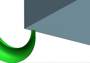
Cashew Gate
Attached are some pictures that show the geometry changes from the industry standards. The D-gate style sub-gate versus the standard simulates the thin/wide concept and provides much cleaner gate breaks than the standard sub-gate. The other important part of the gate geometry is the mass and taper leading up to the orifice. It should always taper down to the orifice to prevent flow restrictions. If it doesn’t it can cause an increase in fill pressures and in some cases imbalances.
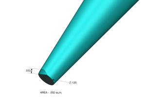
D-Gate with Matching Area
An example of this was on a 2-cavity mold with sub-gates. This mold had a RH and LH part that were exactly mirrored so there was no difference between cavity size, but the cavities were significantly imbalanced. I was asked to open up the sub-gate orifice on the cavity that was short even though the gate orifices were the same size (not always a good idea). After opening the orifice to where it had 50 % more volume I knew something was wrong. I looked closely and found the sub-gate tapers were slightly different, not enough to be noticeable without a very close look. We increased the taper on the cavity that was short to match the taper on the other cavity, and it caused a huge change. The cavity that was short now was way ahead of the other cavity.
With the D-Style sub-gate the taper is taken out of the equation for flow restrictions because there is not a gradual taper of mass like the standard sub-gate. You can also sub-gate into angled walls because you’d end up with gate vestige. Also you can gate into shorter walls with a
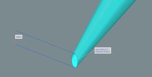
Sub Gate with Dims
standard sub-gate. There are endless opportunities with D-gate orifices. You can increase the tip of the cone on the D-gate to create a wider gate orifice. It’s important to understand the volume of the gate orifice. You can use a much thinner gate orifice because you are increasing volume with the extra width.
It’s About Volume
Pretty much everyone I have discussed gate geometry with over the years automatically assumes you’ll have an increase in fill pressures if you go thinner. I’ve found it’s more about volume with increasing the width whenever I go thinner, and some materials prefer shear with thinner gates.
People say I was flirting with dimensional issues when playing with thinner gates. But with what I’ve learned I think the opposite is true in most cases with larger processing windows along with shorter cycle times. I see nothing but advantages with a larger process window. The reduced quality issues mentioned earlier are convincing enough to the point that I would never build a new tool with a standard sub-gate or cashew gate with the gradual taper to a round orifice unless something with the part geometry prevented me from doing so.